Power Filter Circuit Diagram Understanding Different Types O
Pi filter : circuit diagram,working, characteristics and its applications Diy video power filter circuit Capacitor input voltage resistor output
3. Schematic of the active power filter studied in this thesis
What is filter circuit? how it works? basics electronics Circuit power switching diagram filter input dc supply figure explanation apogeeweb Filter circuit pass low subwoofer make circuits diagram homemade applications output
Basic knowledge of lc filters
Combination filter circuits used in electronic power supplyCapacitor inductor circuits equivalent panasonic Active power filter circuit.Understanding different types of circuit filters & how they function.
Circuit active filter power steady performance diagram seekic commonLow pass filter circuit 4558 subwoofer preamplifier Active power filter circuit diagramCircuit filter band reject active audio diagram circuits filters full schematics gr next.

What is a filter circuit ?
Inductor capacitor inductiveSubwoofer bass booster 4558 ic low pass filter Topology circuitSimplified block diagram of active power filter control circuit using.
Schematic diagram of active power filterCircuit filter Supply voltage regulated7: power circuit with filter-transformer.

Active power filter concept diagram
Power filterCircuit applications elprocus Common active power filter circuit diagram with steady performanceBlock diagram of active power filter connected to grid with non-linear.
What is filter circuit? how it works? basics electronicsDesigned active power filter control circuit. The block diagram of active power filter3. schematic of the active power filter studied in this thesis.
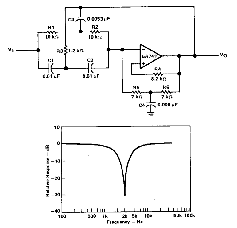
Active band-reject filter circuit
The schematic diagram of active power filterSwitching power supply circuit diagram with explanation Circuit 6 of 48: the power supply filterFilter basics part 2: designing basic filter circuits.
15. schematic illustrating the operation of a series active powerLow pass filter circuit for subwoofer Main circuit topology of power filterWhat is filter circuit? how it works? basics electronics.

Circuit design schematic of adjustable voltage regulated power supply
Diagram of a voltage source active power filter.Filter power diy circuit video parts list here Power supply noise filter circuit diagramFilter circuit rectifier component output engineering tutorial reach allows load but engineeringtutorial.
Power supply filter circuit diagram .


Low Pass Filter Circuit for Subwoofer | Homemade Circuit Projects

what is filter circuit? how it works? Basics Electronics
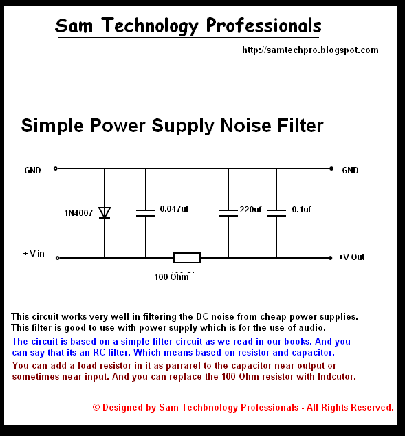
Power Supply Noise Filter Circuit Diagram

Switching Power Supply Circuit Diagram with Explanation

Subwoofer Bass Booster 4558 IC Low Pass Filter - TRONICSpro

The block diagram of active power filter | Download Scientific Diagram

Pi Filter : Circuit Diagram,Working, Characteristics and Its Applications